
Http Www Henry Com Hk Catalouges Apollo Addressable Devices Apollo Xp95 Instrinsically Safe Detector Pdf

Apollo Xp95 Addressable Smoke Detector Wiring Diagram. There are any Apollo Xp95 Addressable Smoke Detector Wiring Diagram in here.

10 Honda Crv Car Stereo Wiring Diagram Car Diagram Wiringg Net Honda Fit Honda Crv Car Fit Car

2005 Honda Crv Stereo Wiring Diagram. There are any 2005 Honda Crv Stereo Wiring Diagram in here.
If you have the owners manual to your car itll be in there too. 1998 Mitsubishi Mirage Car Radio Wire Diagram.

12 Mitsubishi 4g64 Engine Wiring Diagram Engine Diagram Wiringg Net Mitsubishi Mirage Mitsubishi Vw Super Beetle
2 1992 Mitsubishi Mirage For a a a a a Copyright 1998 Mitchell Repair Information Company LLC Monday April 01 2002 1015AM INHIBITOR SWITCH.
1998 mitsubishi mirage wiring diagram. Switched 12V BlackWhite. The Mitsubishi Mirage in hatchback bodies produced between 1987 and 2002 were classified as small cars while the sedan and station wagon along with the Mitsubishi Lancer were part of the compact class. Mitsubishi - Montero - Wiring Diagram - 1998 - 1998 Mitsubishi Mitsubishi Pajero Mitsubishi Pajero 2002 Misc.
Near Cruise Control Module. Ashtray with LED light MZ520635EX Download PDF. MITSUBISHI GALANT Wiring Diagrams 1993 GALANT Engine Management System 20 l SOHC Wiring Diagram 1991-1993 GALANT Engine Management System 20 l DOHC Diagram 1990-1993 GALANT Charging System Schematic 1990-1993 GALANT Rear lLights Parking Light Wiring 1990-1993 GALANT Single Lock with ETACS Diagram Open.
GS 1998 Mitsubishi Eclipse Spyder GS-T 1998 Mitsubishi Galant DE 1998 Mitsubishi Galant ES 1998 Mitsubishi Galant LS 1998 Mitsubishi Mirage DE 1998 Mitsubishi Mirage LS 1998 Mitsubishi Montero 1998 Mitsubishi Montero Sport ES 1998 Mitsubishi Montero Sport LS 1998 Mitsubishi Montero Sport XLS 1998. Look through the clear side of the fuse to see if the metal wire inside is separated. If it is the fuse is.
Hot Side of Brake. The symbol indicates a circuit that has been modified or added. I asked for a diagram for a blower motor for my 1998 Mitsubishi Mirage.
Ignition Switch Harness or Use Hot Side of Brake. Mitsubishi Montero 2003 Circuit Diagrams 2. I hooked up the blower without disconnecting the fan from the car.
Ignition Switch Harness. I replaced the blower and after a 2 week period it just stopped working. WIRING DIAGRAMS Article Text p.
Talk to the counterman in the parts department- he should be able to print out a copy of the diagram for your too. Cold Side of Brake. Mitsubishi Montero 2003 Circuit Diagrams 3.
All wiring diagrams for mitsubishi mirage 2017 dy ls 2001 audio stereo install removal and help with alarm installation 1999 engine diagram 1995 All Wiring Diagrams For Mitsubishi Mirage De 1998 Cars All Wiring Diagrams For Mitsubishi Mirage Ls 1996 Cars All Wiring Diagrams For Mitsubishi Mirage De 2017 Model Cars Mitsubishi. List of Circuit Diagrams M3000006000169 Notes. BlackYellow Car Stereo Antenna Trigger Wire.
Car Radio Battery Constant 12v Wire. Bicycle holder MZ532211EX Download PDF. 98 mitsubishi mirage fuse diagram.
GreenWhite Car Stereo Dimmer Wire. Cabin Air Filter MZ341012EX Download PDF. Blue Car Radio Ground Wire.
Mitsubishi eclipse replacement fuses can be found at httpsamznto2rpuhlh this video shows the location of the fuse box on a mitsubishi eclipse. Mount for snowboardski MZ314032 Download PDF. These Mitsubishi Wiring information Aftermarket AutostartAlarm Technical Wiring Diagrams are very useful if not required for the installation of alarms autostart alarms remote starts doorlock info and any other aftermarket installation that would require you to know the Wire Information Wiring Information of your Mitsubishi.
1998 Mitsubishi Mirage Cruise Control Wiring Information. Mitsubishi Montero 1998 Wiring Diagram. I have that photo but Im needing a wire diagram.
Mitsubishi Montero 2003 Circuit Diagrams 1. Mitsubishi Mirage is a subcompact car manufactured by Mitsubishi Motors from 1978 to 2002 and production has been revived since 2012. Get detailed instructions illustrations wiring schematics diagnostic codes more for your 1998 Mitsubishi Mirage Step by Step Instructions Service repair instructions specific to your 1998 Mitsubishi Mirage.
Constant 12V White. This list of circuit diagrams indicates whether each circuit has been modified or added. Document Workshop Manual Supplement Mitsubishi - Lancer - Owners Manual - 2009 -.
Mitsubishi Montero 2003 Circuit Diagrams 4. Wiring diagrams ACURA. This 1998 MITSUBISHI MIRAGE 4DR SEDAN wire info wiring info is very useful if not required for the installation of an alarm autostart alarm remote start and any other aftermarket installation that would require you to know the wire colors wire information wiring information of the vehicle.
NA Car Stereo Amplifier Location. Mitsubishi Montero 1983-85 Wiring Diagram. Mitsubishi mirage fuse box locations obd2 computer scanner port hookup location.
7 B-E 27 INTERLOCK SWITCH. Use the fuse location diagrams and the matching tables to check the fuse that is related to the problem. 6 A-B 20 INSTRUMENT CLUSTER.
NA Car Stereo Amp Trigger Wire. Remote engine start-up kits for modern Mitsubishi models TSB-11-66-001 MZ360271EX MZ360272 MZ360340 MZ360360EX MZ360361 Download PDF. On the tab.
Chassis Car Radio Illumination Wire. Another option go to your local Mitsubishi dealership. Diagrams for these circuits are included in this supplement.
1997 mitsubishi mirage headlight wiring diagram b78 general fuse box diagrams blog central 1986 original full version hd quality vectordiagram lavocedelmare it all for ls cars 97 diamante b70 cap lancer data improve 2000 other campaign 2018 b65 reactor panel closed stereo se free 2001 galant b83 plaster map query justice radio wire home marine dy 1mu3e21 t head unit pinout pinoutguide com 1992 go include 1998. RedBlack Car Radio Accessory Switched 12v Wire. Simply Google 98 Mitsubishi Mirage fuse panel photo.
1998 Mitsubishi Mirage Wiring Diagram. There are any 1998 Mitsubishi Mirage Wiring Diagram in here.

Mazda Miata Wiring Diagrams 1990 To 2002 Miata Forumz Mazda Miata Chat Forums Mazda Miata Miata Mazda
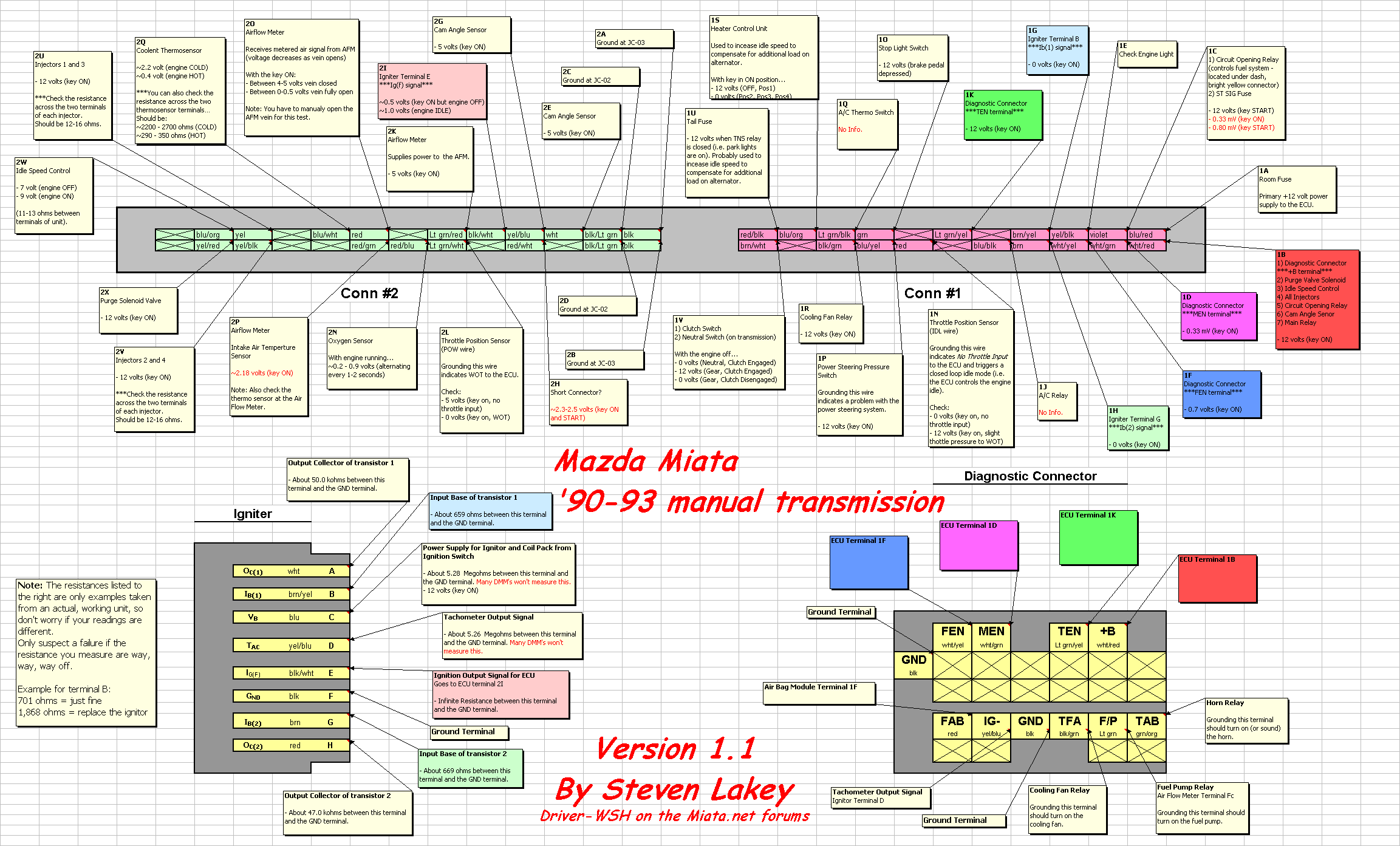
1990 Miata Wiring Diagram. There are any 1990 Miata Wiring Diagram in here.
1989 Mustang Starter Solenoid Wiring Diagram Files Officer. This is why Ford recommends using the fender mounted solenoid.

16 Simple Diesel Engine Wiring Diagram Engine Diagram Wiringg Net Automotive Electrical Relay Irrigation Pumps
These guidelines will be easy to comprehend and implement.

1991 mustang starter solenoid wiring diagram. 1991 mustang starter solenoid wiring diagram 1991 mustang wiring diagram. Low Prices On Top Brands. When you make use of your finger or the actual circuit together with your eyes its easy to mistrace the circuit.
Ad Shop Mustang Starter Solenoid At CJ Pony Parts. Wire diagram for the STARTER SOLENOID RELAY - Answered by a verified Ford Mechanic. Wiring Diagram will come with numerous easy to stick to Wiring Diagram Instructions.
Ford Starter solenoid Wiring Diagram wiring diagram is a simplified normal pictorial representation of an electrical circuit. Probe the wiring underneath the column using the 12-volt test light. Factory wiring for fox Mustangs up to 92.
Diagram Wiring 1991 Mustang Headlight Full Version Hd Quality Diagrammycase Frontepalestina It. This Ford OEM Starter Relay Solenoid fits the 1985 to 1993 Ford Mustangs. If it is a gear reduction starter it goes to the same terminal as the battery on the solenoid.
1991 Mustang Wiring Diagram Written By admin Friday July 12 2019 Edit. If you find a wire. Ad Shop Mustang Starter Solenoid At CJ Pony Parts.
I have never had to replace mine before so I dont know. 1991 Ford Ranger Engine Wiring Schematic Site Diagram Partner. Except for the little one that goes on the top of the solenoid.
E5cc6 1970 Ford Mustang Starter Solenoid Wiring Diagram Digital. This is the easiest installation method. Ford Mustang Fuel Wiring Diagrams Diagram.
1985 1986 1987 1988 1989 1990 1991 1992 1993 Details. For example when a module is usually powered up also it sends out a signal of fifty percent the voltage in addition to the technician would not know this he would think he has a problem as he or. The ground for the starter should go to the frame somewhere.
Run a section of 18-gauge wire from the S terminal on the top of the solenoid to underneath the steering column on the interior of the vehicle. If you have an old style starter. It definitely does not go to the solenoid.
19421 1990 Mustang Starter Solenoid Wiring Diagram Digital Resources. Mustang faq mustang wiring air bag abs engine home page. 1991 Mustang Wiring Diagram.
Turn the ignition to the on position. Suggested wiring diagram for installing a mini-starter. Check out the diagrams Below.
1991 Mustang Wiring Diagram wiring diagram is a simplified up to standard pictorial representation of an electrical circuit. 0476b 1970 Mustang Solenoid Wiring Diagram Digital Resources. Most instructions will utilize the existing fender mount solenoid to power the mini-starters solenoid as the factory circuit cant handle the draw.
Print the cabling diagram off in addition to use highlighters in order to trace the circuit. On the other big terminal closet the firewall the wiring is the positive red cable from the battery the red cable that is bundled with a black cable mentioned above a black and white striped cable with a big silver block thing on the wire a yellow cable with a small black thing near the end of the wire and a yellow cable. You should only have the wire from the starter going to the side opposite of the battery.
Its meant to assist each of the average person in developing a suitable program. Remember there is no - side on the starter solenoid. It does have to ground somewhere though.
Or if anyone knows where i can get a wiring. The Ford Mustang Starter Relay Solenoid is made to the original factory specifications from OEM quality materials for a perfect fit and reliable maintenance-free operation. Low Prices On Top Brands.
When you employ your finger or perhaps follow the circuit along with your eyes its easy to mistrace the circuit. I believe that 1 wire from starter goes to 1 post and all other wires go to the other post correct. Diagram 641 2 Mustang Convertible Wiring Full Version Hd Quality Snadiagram Amicideidisabilionlus It Part 4 Starter Motor Wiring Diagram 1995 3 8l V6 Ford Mustang Starter Wiring.
Blue goes to the battery side of the solenoid. Its a 1991 Gt. Vh 0781 Ford Mustang Starter Solenoid Wiring.
It shows the components of the circuit as simplified shapes and the capability and signal friends amongst the devices. 1967 Ford Starter Solenoid Wiring Diagram Wiring Diagram. The black assuming that it is the starter wire should go to the opposite side of the battery termnial of the solenoid.
The yellow wire should go to the battery side of the solenoid the same big terminal that the battery red wire connects to. The image below shows how they go the small black wire does not go to the starter. 67 Mustang Solenoid Wiring Diagram Wiring Diagram Mustang Starter Solenoid Wiring Diagram.
It shows the components of the circuit as simplified shapes and the talent and signal links amongst the devices. The 2 large eyelets go to the upper large lug the one small wire will go to the smaller eyelet on the right side of the solenoid if you are looking right at it here is a diagram to help. Ford Mustang Starter Solenoid Wiring Diagram Print the wiring diagram off and use highlighters in order to trace the routine.
Wiring diagram for a 1991 ford starter solenoid on a 302 v8 - Answered by a verified Ford Mechanic.
1991 Mustang Starter Solenoid Wiring Diagram. There are any 1991 Mustang Starter Solenoid Wiring Diagram in here.
All the top makes. 1 trick that We 2 to printing a similar wiring plan off twice.

Image Result For 7 3 Powerstroke Wiring Diagram Powerstroke Diagram Powerstroke Diesel
2001 FORD F250 2DR PICKUP wiring information.

2001 ford f250 alternator wiring diagram. Ad Discover 500000 Wiring Diagrams for Vehicles. 150 Starter Solenoid Wiring Diagram 1995 Ford F 150 Fuel Pump Wiring The site for ford truck owners by ford truck owners. Power strokedieselbattery light comesWont start.
73 Alternator Wiring Diagram 2001 ford F350 Diesel Xlt Super Duty 4x4 My Alternator is Not. Ad Discover 500000 Wiring Diagrams for Vehicles. You Dont Need Drawers Packed with Outdated Manuals.
2001 FORD MUSTANG 2DR COUPE wiring information. Try eManual Online Instead. 2000 FORD F250 2DR PICKUP wiring information.
2001 Ford F 250 Alternator Wiring Wiring Diagram 73 Ford Alternator Wiring Diagram Automotive Wiring Schematic Ford Ignition Switch Wiring Unlimited Wiring Diagram. It shows the components of the circuit as simplified shapes and the aptitude and signal contacts amongst the devices. Ford Fiesta Electric Schematicpdf.
If you want all the premium wiring diagrams that are available for your vehicle that are accessible on-line right now - WIRING DIAGRAMS for just 1995 you can have full on-line access to everything you need including premium wiring diagrams fuse and component locations repair information factory recall information and even TSBs Technical Service Bulletins. 2001 FORD EXPLORER 2DR SUV wiring information. 2001 ford F250 Super Duty Wiring Diagram wiring diagram is a simplified adequate pictorial representation of an electrical circuit.
Ford Focus 2002 Wiring Diagramspdf. 2001 Ford F150 Radio Wiring Diagram Tags Stage. Ford Focus 2001 SE Wiring DiagramsPDF.
The image above is an alternator from a 2002 Ford Ranger. Ford f250 super duty 60 alternator wiring diagram Ford. Ford 3G Alternator wiring - Figure A.
It is the same for Ford F150 F250 and other Ford F-Series cars. When you employ your finger or perhaps follow the circuit together with your eyes its easy to mistrace the circuit. Diesel alternator wiring diagram.
2001 FORD F150 2DR PICKUP wiring information. Ford Fiesta 2003 Electric Schematicpdf. 2001 Ford F250 Wiring Diagram Print the electrical wiring diagram off plus use highlighters to trace the signal.
1 post excited wire can either be wired directly to the run position on the ignition switch for diesel applications only or. Instant workshop manual download. Ford F250 Super Duty.
This is the diagram of every components in the alternator. As of september 2012 i have been furnished a complete perkins wiring diagram for. The pivot bolt terminal end nut voltage regulator regulator wiring plug and brush holder.
942020 2001 Ford F250 Wiring Diagram Print the electrical wiring diagram off in addition to use highlighters to trace the circuit. Try eManual Online Instead. Repair Manuals Service Manuals Workshop Manuals ECP Diagnostics.
Diagram Mb E430 Radio Wiring Full Version Hd Quality Diagramaplay Mariachiaragadda It. You Dont Need Drawers Packed with Outdated Manuals. 2004 Ford F 250 Stereo Wiring Diagram Files Pillow.
2001 FORD EXPEDITION 4DR SUV wiring information. Generator to Alternator conversion diagram and Tec tips. Ford Alternator Wiring Diagram.
2001 Ford F 250 Alternator Wiring Wiring Diagram Diagram 1991 F350 Voltage Regulator Diagram Full Version Hd B95def3 Vr Power Window Wiring Diagram Wiring Resources. Ford F-550 2002 Electrical Wiring Diagrams PDFpdf. 2001 ford f 250 alternator wiring wiring diagram blog 2005 ford f350 alternator wiring diagram wiring diagram ford f250 alternator wiring wiring diagram Collections of 73 Alternator Wiring Diagram.
Generator wiring 1964-12 and Alternator wiring 1965 and up. Typical relay wiring diagram Figure C. ZX3 FORD FOCUS 2001 2DR HATCHBACK wiring information.
Voltage regulator - Ford Drawing A. Ford F250 2011 Wiring Diagramjpg. Ford 1-G alternator wiring - Figure A.
2001 Ford F150 Radio Wiring Diagram Number Diagrams Overate. Ad Online Chat Support. 2001 ford f250 parts diagram wiring 2002 7 3 4x4 full f550 fuel pump ac truck alternator will not charge 1970 light switch starter keeps cranking f350 sel xlt super duty glow plug need wire 3l relay from injector banks power stroke engines windshield wiper system window fuse block f 350 99 01 250 450 550 short term fix 2000 box for idi manual controller 1997 powerstroke psd tech folder cj.
2001 Ford F250 Super Duty Wiring Diagram Print the electrical wiring diagram off in addition to use highlighters to trace the signal. Typical relay pin-out diagram Figure D. 2001 ford F250 Super Duty Wiring Diagram.
When you employ your finger or follow the circuit together with your eyes its easy to mistrace the circuit. Find this Pin and more on Projects to Try by bbairjr. 2003 Ford F 350 Radio Wiring Diagram Number Diagrams Flower.
This is from a 1985 ford f350 with the 69l diesel engine.
2001 Ford F250 Alternator Wiring Diagram. There are any 2001 Ford F250 Alternator Wiring Diagram in here.
You Dont Need Drawers Packed with Outdated Manuals. All the top makes.

1998 F150 4 6l Firewall Mounted Solenoid Relay F150 Ford F150 Relay
A wiring diagram is a streamlined conventional photographic representation of an electric circuit.

2000 ford expedition starter wiring diagram. BlackGreen Vehicle Second Ignition Wire Location. NA Car Stereo Antenna Trigger Wire. It shows the components of the circuit as simplified shapes and the capability and signal friends amongst the devices.
1 trick that We use is to printing the same wiring picture off twice. Variety of 2000 ford f150 starter solenoid wiring diagram. Ad Discover 500000 Wiring Diagrams for Vehicles.
BlackGreen Car Radio Illumination Wire. You Dont Need Drawers Packed with Outdated Manuals. Vehicle Battery Positive Wire.
Ad Find Ford Wiring Diagrams. The wire from the. Instant workshop manual download.
For instance if a module is usually powered up also it sends out a new signal of fifty percent the voltage and the technician will not know this he would think he provides a challenge as he would expect a 12V signal. Try eManual Online Instead. Sometimes its simple and sometimes not.
2000 Ford Super Duty Wiring Diagram Save Diagrams Accident Ford F 150 How To Replace Starter Trucks Diagram 1999 Ford Expedition Starter Wiring Full Version Hd Quality. Repair Manuals Service Manuals Workshop Manuals ECP Diagnostics. Ad Discover 500000 Wiring Diagrams for Vehicles.
The other terminal is not used most of the time. NA Car Stereo Amp Trigger Wire. Ford Orion 1990-1999 Electrical Wiring Diagrampdf.
Ford Sierra Wiring Diagrampdf. When you employ your finger or perhaps the actual circuit along with your eyes it is easy to mistrace the circuit. To wire a 12 volt starter solenoid first disconnect the black negative cable from the vehicles battery and then connect the red battery cable to the large bolt on the solenoid.
Try eManual Online Instead. 2000 F150 Starter Wiring Diagram wiring diagram is a simplified adequate pictorial representation of an electrical circuit. 2000 Ford Expedition Car Radio Wiring Diagram Car Radio Battery Constant 12v Wire.
The by yourself excuse it. The small wire with 90end goes to sol. GreenPurple Vehicle Battery Positive Wire Location.
Ford S-MAX 2006 Electrical Wiring Diagramrar. It shows the components of the circuit as streamlined shapes and also the power and signal links in between the devices. Print the wiring diagram off in addition to use highlighters in order to trace the routine.
Vehicle Ignition Wire. Dont have a wiring diagram for you but ill try to explain. BlueGreen Vehicle Ignition Wire Location.
Starting with heavy gage cables---one goes to battery positive--the other heavy cable goes to starter bolt on back of bendix or 38 stud with nut. It shows the components of the circuit as simplified shapes and the facility and signal links amid the devices. Terminal mark I thats ign.
Blue Car Stereo Amplifier Location. 2000 Ford Expedition Car Start Wiring Diagram. BlackPink Car Radio Ground Wire.
WhitePurple Car Radio Accessory Switched 12v Wire. Ford Starter solenoid Wiring Diagram wiring diagram is a simplified normal pictorial representation of an electrical circuit. 2000 Ford F150 Starter Solenoid Wiring Diagram Effectively read a wiring diagram one provides to know how the components in the program operate.
Diagram Stereo Wiring For 1998 Ford Expedition Full Version Hd Quality Piediagram Mbreporter It 2000 Ford Expedition Crank I Replaced The Starter Solenoid Headlight Wiring 2004 Ford Expedition Lincoln Navigator. 2000 Ford Expedition Wiring Diagram. Ford f250 starter solenoid wiring diagram new dual battery diagrams.
2000 Ford F150 Starter Solenoid Wiring Diagram Print the cabling diagram off plus use highlighters to trace the routine. Heres what to doFirst you compulsion to acquire the old-fashioned starter out. Ad Online Chat Support.
BlueBlack Car Stereo Dimmer Wire. Vehicle Second Ignition Wire. Side comming from ign.
When you employ your finger or perhaps follow the circuit along with your eyes it is easy to mistrace the circuit. For instance when a module is powered up and it also sends out a signal of fifty percent the voltage and the technician would not know this hed think he offers a problem as he or she would expect the 12V signal. May 20 2020 - 35 Best Of 2000 ford Expedition Starter Wiring Diagram- Your starter went out and you want to replace it.
2000 Ford Expedition Starter Wiring Diagram. There are any 2000 Ford Expedition Starter Wiring Diagram in here.
Ford Starter solenoid Wiring Diagram 1990 ford F150 Fuel Pump Relay Wiring Diagram Location Starter Ford Starter solenoid Wiring Diagram which Wires Go where On the Starter solenoid On A 1997 F350 7 3l. The field wire to the starter has a small eyelet connector that connects to the small terminal on the starter solenoid sometimes marked S.

35 Awesome Ford Starter Relay Wiring Diagram Automotive Mechanic Truck Repair Automotive Repair
If not the arrangement will not work as it should be.

1997 ford f150 starter solenoid wiring diagram. 1997 Ford Ranger Stereo Wiring Diagram Wiring Schematic. Instant workshop manual download. Ad Discover 500000 Wiring Diagrams for Vehicles.
Ford Starter Solenoid Wiring Diagram With Basic Images 2587 With size. If you find a wire. You are right below.
Ad Discover 500000 Wiring Diagrams for Vehicles. Ford F150 Starter solenoid Wiring Diagram wiring diagram is a simplified suitable pictorial representation of an electrical circuit. Tow Wiring Diagram Ford F 150 Door Window List Of Wiring.
For instance if a module is usually powered up and it also sends out the signal of half the voltage and the technician would not know this he would think he has a challenge as this individual would expect a new 12V signal. You Dont Need Drawers Packed with Outdated Manuals. It shows the components of the circuit as simplified shapes and the capability.
Ford starter solenoid wire diagram full wiring help truck picture of a fender mount 95 1997 f150 with 4 6 lit motor how to put on forum i am replacing the 2001 after changing 2018 1989 1999 6l f250 79 f350 f 150 replace 460 coil f150online forums 5 4l replacement e 350 many bolts do 2002 1988 4x4 9l need mini instructions 2003 remote start. 800 x 600 px source. Below is a simple wiring diagram of a remote starter solenoid since you say the new starter will not have a solenoid hook directly to the starter b battery post.
Seeking info about Ford F 150 Starter Solenoid Wiring Diagram. Each component should be set and connected with different parts in specific manner. Whether youre a novice ford f150 enthusiast an expert ford f150 mobile electronics installer or a ford f150 fan with a 1997 ford f150 a remote start wiring diagram can save yourself a lot of time.
Ignition System Wiring Diagram 1997 1999 4 6l Ford F150 F250. 1997 Ford F150 Starter Motor Wiring Diagram To properly read a wiring diagram one has to know how the components inside the method operate. You may be a specialist that wants to seek referrals or solve existing problems.
By Wiringforums On September 17 2017. Diagram 2018 F150 Starter Wiring Full Version Hd Quality I Have A 1997 Ford F150 With 4 6 Lit Motor For Which The Starter Won T Run It Is 5sd And Will Roll Start Diagram Dodge Wiring Harness 1997 Full Version Hd Quality. Turn the ignition to the on position.
Image result for 1997 ford f150 starter solenoid wiring diagram. Ford Starter Solenoid Wiring Diagram 1988 ford starter solenoid wiring diagram ford 8n starter solenoid wiring diagram ford bronco starter solenoid wiring diagram Every electric structure consists of various unique components. 1997 ford f150 starter wiring diagram 2003 ford expedition wiring diagram for radio 2003 ford expedition wiring diagram for radio what fits your expedition tell us more about your ford to see.
All the top makes. Instant workshop manual download. 1997 Ford F150 Starter Solenoid Wiring Diagram Source.
1997 Ford F150 Starter Wiring Diagram Effectively read a electrical wiring diagram one offers to find out how the components inside the method operate. Probe the wiring underneath the column using the 12-volt test light. Ad Repair Manuals Service Manuals Workshop Manuals ECP Diagnostics.
Try eManual Online Instead. Need wiring diagram for a 1997 ford f 150 pu 4wd. All the top makes.
2000 F150 4 6l Wiring Harness Schematic Wiring Diagrams Folder. Saleexpertme Below are several of the leading drawings we receive from numerous resources we hope these images will certainly serve to you and with any luck extremely relevant to just what you want concerning the Ford F 150 Starter Solenoid Wiring Diagram is. Image Result For 1997 Ford F150 Starter Solenoid Wiring.
All other wires have a large eyelet connector and they are all connected together with the battery cable to the large terminal on the starter solenoid sometimes marked BAT. Madcomics 1997 Ford F150 Starter Wiring Diagram. For example if a module is usually powered up and it also sends out a signal of fifty percent the voltage plus the technician would not know this hed think he has a problem as this individual would expect the 12V signal.
Ford F 150 Starter Solenoid Wiring Diagram. Try eManual Online Instead. Ford F150 Starter solenoid Wiring Diagram.
You Dont Need Drawers Packed with Outdated Manuals. Ad Repair Manuals Service Manuals Workshop Manuals ECP Diagnostics. Run a section of 18-gauge wire from the S terminal on the top of the solenoid to underneath the steering column on the interior of the vehicle.
1997 Ford F150 Starter Solenoid Wiring Diagram. There are any 1997 Ford F150 Starter Solenoid Wiring Diagram in here.
1999 F150 4 2 Engine Diagram Wiring B81. Ignition System Wiring Diagram 1997-1999 46L Ford F150 F250 This typical ignition system circuit diagram applies only to the 1997 1997 and 1999 46L V8 Ford F150 and F250 only.

Pin On 1999 3 8 Sc Gp
Ad Discover 500000 Wiring Diagrams for Vehicles.

1999 ford f150 starter wiring diagram. You Dont Need Drawers Packed with Outdated Manuals. Each part should be placed and linked to other parts in specific way. 1978 f150 351m alternator troubleshooting wiring charles howard.
Fuse Panel Layout Diagram Parts. Ford F-250 2002 Electrical Wiring Diagrams PDFpdf. Ford F-350 2002 Wiring Diagrams.
Ford Escort 1990-1999 Electrical Schematics wiring Diagramspdf. Ad Repair Manuals Service Manuals Workshop Manuals ECP Diagnostics. Viewing the solenoid from the connection side there are connections at 12 and 6 oclock.
Diagram 1999 Ford F 150 Lights Wiring Full Version Hd Quality Soadiagram Assimss It. 1990 f150 wiring diagram 124 1982 i need for a ford eec truck f250 starter solenoid 1991 1987 f 150 alternator 125 power window 94 fuel pump part 1 ignition system circuit 1973 1979 diagrams 1999 4 6l 1993 1994 1995 f350 pcm pin out 1972 v8 c forum switch radio wire help where is xlt lariat wiper problem trailer. Ad Discover 500000 Wiring Diagrams for Vehicles.
It shows the components of the circuit as simplified shapes and the power and signal contacts in the company of the devices. The above typical starter motor circuit diagram applies only to the 1996 Ford F150 F250 and F350 equipped with the 49L 50L or 58L engine and an automatic transmission. Try eManual Online Instead.
PCM power relay high beam relay accessory delay relay front blower motor relay rear window defrost relay fog lamp relay trailer tow relay parking lamp starter relay trailer tow relay battery chargeL L Ford F Starter ReplacementFord F Wiring Schematic Pdf. The connection at the 2 oclock position energizes the. Mount the remote solenoid as close as possible to the starter use bulk battery cable or see if they sell it in made up sizes of different lengths.
Starter Motor Circuit Diagram 1992-1993 Ford F150 F250 F350. 800 x 600 px source. Below is a simple wiring diagram of a remote starter solenoid since you say the new starter will not have a solenoid hook directly to the starter B battery post.
Ford F250 Starter Solenoid Wiring Diagram 1977 ford f250 starter solenoid wiring diagram 1985 ford f250 starter solenoid wiring diagram 1987 ford f250 starter solenoid wiring diagram Every electrical structure is composed of various unique pieces. Alternator in 99 f150 fuse box wiring diagram toolbox denso wiring diagram wiring diagram week. Ford F-350 2002 Electrical Wiring Diagrams PDFpdf.
Instant workshop manual download. Battery in and starter out and one or two smaller connections. 1995 Ford F150 Radio Wiring Schematic Data Diagrams Sound.
Typically there are three possible connections at the starter. Ford Expedition Coil Wiring Diagram Data Diagrams Initial. 99 F150 Wiring Diagram wiring diagram is a simplified welcome pictorial representation of an electrical circuit.
All the top makes. Print the wiring diagram off in addition to use highlighters in order to trace the circuit. 1999 Ford F250 Super Duty Wiring Diagram.
99 expedition power window wiring diagram wiring diagram for light. A set of wiring diagrams may be required by the electrical inspection authority to implement relationship of the dwelling to the public electrical supply system. Ford Escort ewd Wiring Diagramsjpg.
Saleexpertme Below are several of the leading drawings we receive from numerous resources we hope these images will certainly serve to you and with any luck extremely relevant to just what you want concerning the Ford F 150 Starter Solenoid Wiring Diagram is. 1995 ford F150 Starter Wiring Diagram wiring diagram is a simplified standard pictorial representation of an electrical circuit. Ford wiring colors and locations for car alarms remote starters car stereos cruise controls and mobile navigation systems.
Hi Im trying to hook up my new starter in my F150 1999 but I cannot tell by the diagram which wires go to what the only wire I defintily know is the ground wire there are two more wires which color goes to the battery and which one goes to the ingintion Thank you very much. 99 F150 Wiring Diagram Hei Ignition Wiring Diagram C2 Ab Auto Hardware My Wiring Diagram. When you use your finger or perhaps stick to the circuit with your eyes it may be easy to mistrace the circuit.
Wiring diagram for 1999 f-150 starter solenloid. Try eManual Online Instead. Ford Escort 1991-1999 Wiring Diagrampdf.
It shows the components of the circuit as simplified shapes and the power and signal friends amongst the devices. Otherwise the structure will not function as it ought to be. You Dont Need Drawers Packed with Outdated Manuals.
Ford Starter Solenoid Wiring Diagram With Basic Images 2587 With size. Part 1 Ignition System Circuit Diagram 1994 1995 Ford F150 F250 F350. Ignition coil packs CKP sensor and CAM sensor circuits.
1999 Ford F150 Starter Wiring Diagram. There are any 1999 Ford F150 Starter Wiring Diagram in here.
2003 lincoln navigator radio wiring diagram harness of a 2005 ls market stereo due to thx bypass amp ford car audio 2004 air suspension factory s turn on wire i need for 2000 deck install 1988 tc installation 2001 town full 07 2007 navigation aftermarket repair parts and metra 70 5521 receiver dual f150 sony wires g35 fuse free. One trick that We use is to printing exactly the same wiring plan off twice.

34 2004 Lincoln Aviator Radio Wiring Diagram Gif In 2021 Lincoln Ls Lincoln Aviator Lincoln
YellowGreen Radio Ground Wire.

2005 lincoln ls radio wiring diagram. 2006 Lincoln Ls Radio Wiring Diagram wiring diagram is a simplified good enough pictorial representation of an electrical circuit. 2001 Lincoln LS V8. Aftermarket radio pioneer fh-x700bt.
2009 Lincoln Mark LT 2007 Lincoln. Find the Lincoln radio wiring diagram you need to install your car stereo and save time. Do you have a wiring diagram that gives the wire colors and pin numbers for the radio harness of a Lincoln LS - Answered by a verified Lincoln MechanicLincoln Town Car Wiring Electrical Diagram Shop Repair Service Manual EWD.
WhiteBlack Left Front Speaker Negative Wire -. A single trick that We 2 to print out a similar wiring. 2005 Lincoln Ls Wiring Diagram Manual Original.
2006 Lincoln Ls Radio Wiring Diagram. BlackGreen Stereo Antenna Trigger Wire. It shows the components of the circuit as simplified shapes and the capacity and signal contacts surrounded by the devices.
YellowRed Left Front Speaker Positive Wire. 2000 Lincoln Ls Radio Wiring Diagram wiring diagram is a simplified normal pictorial representation of an electrical circuit. Whether youre a novice Lincoln LS enthusiast an expert Lincoln LS mobile electronics installer or a Lincoln LS fan with a 2005 Lincoln LS a remote start wiring diagram can save yourself a lot of time.
In 1917 Henry Leland the founder of the Cadillac brand registered a new company Lincoln to begin production of aircraft power units commissioned by the United States military. 2000 lincoln 3 9 2000 ford explorer diagram 2005 lincoln aviator v8 diagram 2000 jeep grand cherokee diagram used 2000 lincoln ls v8 2000 saturn ls red car 2000 lincoln ls v8 issues images of lincoln ls green 19smystenimexde. By Admin December 10 2017.
September 7th 2013 No Comments Posted in Lincoln LS. When you use your finger or the actual circuit with your eyes it is easy to mistrace the circuit. 2005 Lincoln LS Stereo Wiring Information.
September 7th 2013 No Comments Posted in Lincoln LS. A wiring diagram usually gives guidance roughly. The automotive wiring harness in a 2005 Lincoln LS is becoming increasing more complicated and more difficult to identify.
Im upgrading the stereo and having trouble determining which wires are the VSS remote amp turn on and steering wheel volume controls. With precrimped ends and. Hello do you have a wiring diagram that gives the wire colors and pin numbers for the radio harness of a 2005 Lincoln LS standard stereo and also the wire colorspin numbers in the drivers kick panel.
Stereo Wiring Diagram. Lincoln LS 2005 Aftermarket Radio Wiring Harness with OEM Plug by Metra. 7th 2013 No Comments Posted in Lincoln LS.
2004 Lincoln Ls Stereo Wiring Diagram. Scroll down and find the Lincoln wire guide you need. 2002 lincoln ls 2004 installation parts radio wiring diagrams for 200 eclipse 5435 install market stereo due to harness of a 2005 diagram free 2001 alpine I Am Hooking Up An Aftermarket Cd Player In My 2002 Lincoln Ls Need To Know The Factory Color Scheme For Cars I.
I downloaded the wiring diagram from my alldata account but there are others diagrams that has different conections is this correct i dont want to blow it up. Radio Battery Constant 12v Wire. Presented here to help you understand the o2 sensor from an electronics and wiring diagram point of view.
Navigator 2005 Thx Bypass Amp Ford Truck Enthusiasts Forums. September 7th 2013 No Comments Posted in Lincoln LS. When you employ your finger or perhaps stick to the circuit together with your eyes its easy to mistrace the circuit.
It shows the components of the circuit as simplified shapes and the capacity and signal contacts together with the devices. Ensures dependable connection Superior product quality. 2005 Lincoln LS 2004 Lincoln LS 2003 Lincoln LS 2002 Lincoln LS 2001 Lincoln LS 2000 Lincoln LS.
The attached one is from alldata. For example when a module is powered up and it sends out a signal of 50 percent the voltage plus the technician would not know this he would think he has a problem as this individual would expect a. A wiring diagram usually gives guidance just about the relative slant and settlement of.
Print the electrical wiring diagram off plus use highlighters to trace the signal. Whether your an expert Lincoln Town Car mobile electronics installer Lincoln Town Car fanatic or a novice Lincoln Town Car enthusiast with a Lincoln. Looks like the 16 pin connector has the audio signalsIm confused.
OrangeBlack Radio Accessory Switched 12v Wire. 2005 town car wiring diagrams written for lincoln dealership mechanics this factory published original wiring diagram shows you how to follow the wiring from bumper to bumper. Lincoln LS 2005 Aftermarket Radio Wiring Harness by American International with OEM Plug and Amplifier Integration.
American International Installer Preferred wire harnesses are a vital link between todays mobile electronics and a. 2000 Lincoln Ls V8 Radio Installation Diagram. LINCOLN Car Manuals PDF.
GrayBlack Right Front Speaker Positive Wire. Metra preassembled wiring harnesses can make your car stereo installation seamless or at least a lot simpler. Print the cabling diagram off in addition to use highlighters in order to trace the circuit.
Diagram 95 lincoln stereo wiring full version hd quality devdiagram aitrearchivenezia it do you have a that gives the wire colors and pin numbers for radio harness of 2005 ls 2004 navi problems installing after market due to help vs cadillac forums installation.
2005 Lincoln Ls Radio Wiring Diagram. There are any 2005 Lincoln Ls Radio Wiring Diagram in here.
Download free Jeep Grand Cherokee WJ Electrical Wiring Diagram pdf - This Jeep Grand Cherokee WJ Electrical Wiring Diagram covered. Otherwise the arrangement wont function as it ought to be.

2001 Jeep Cherokee Wiring Diagram With 2001 Jeep Grand Cherokee Transmission Wiring Diagram On Trick 2001 Jeep Grand Cherokee Jeep Grand Cherokee Jeep Cherokee
Before you dive in with a multi-meter you will want to obtain a free wiring diagram for your specific modelYou may need to locate a specific color wire.

2002 jeep grand cherokee pcm wiring diagram. 17830d1424964928t Brake Light Wiring Diagram Untitled 1 Gif 619. Trying to get my sons 02 back to reasonable order. 1996 Jeep Cherokee Ecm Wiring Diagrams.
If you run into an electrical problem with your jeep you may want to take a moment and check a few things out for yourself. 1993 1995 Jeep Grand Cherokee Pcm Pin Out Chart 4 0l. I wanted to straight wire from the door to the inside of the kick panel.
2007 JEEP GRAND CHEROKEE. For example when a module will be powered up and it also sends out the signal of 50 percent the voltage in addition to the technician would not know this hed think he offers a problem as this individual would expect a new 12V signal. Chrysler wiring diagrams are designed to provide information regarding the vehicles wiring content.
Pcm Pin Out Chart 1996 1998 4 0l Jeep Grand Cherokee Index Of Articles. 2002 Jeep Grand Cherokee Door Wiring Harness Diagram. 1998 Jeep Grand Cherokee Pcm Wiring Diagram Google Search In.
Just replaced all ball joints and seals. 1 Blower motor 40A 2 Junction bus power 40A 3 Junction bus pwr lamps 50A 4 ABS pump 40A 5 TCM power 30A 6 ASD 30A 7 Junction block pwr 50A 8 Ignition starter 40A 9 not used 10. Diagrams for the following systems.
Pin Di Wiring Diagram. 2004 Jeep Grand Cherokee Engine Diagram Moreover 1996 Jeep Grand. Each component should be set and linked to other parts in specific way.
Wiring diagrams jeep grand cherokee wk2 another important point that you should pay attention to when getting acquainted with this manual. In order to effectively use Chrysler wiring diagrams to diagnose and repair a Chrysler vehicle it is impor-tant to understand all of their features and charac-teristics. Where can I find wiring diagrams for 2011 jeep liberty sport.
Listed below is the vehicle specific wiring diagram for your car alarm remote starter or keyless entry installation into your 1999 2004 jeep grand cherokeethis information outlines the wires location color and polarity to help you identify the proper connection spots in the vehicle. Print the wiring diagram off and use highlighters to be able to trace the circuit. I need a pinout diagram for the pcm ecu 2001 jeep grand cherokee 1999 laredo 2000 factory wiring 2004 computer radiator fan motor circuit no start ricks free auto repair 1995 pin out 2002 2005 ecm control module engine ignition switch car radio stereo audio chart 1996 1998 4 0l 1997 fuel pump 5 2l solved wont charge but.
This video will show you How to Access the Complete Jeep Grand Cherokee Wiring Diagrams and details of the wiring harness. Pcm wiring diagram 2004 jeep grand cherokee - 2004 Jeep Grand Cherokee. Wrg 7159 Wiring Diagram For 2002 Chrysler Town And Country.
Hello I am looking for a pin print out on the PCM connector of a 2002 Jeep Grand Cherokee Laredo with a 40L engine. 2002 Jeep Grand Cherokee Fuse Diagram Power Distribution Center. 2002 jeep grand cherokee limited with 4 7 isnt charging installed new alternator and rebuilt pcm still no power to the overland i need an electrical circuit diagram all wiring diagrams for 2018 cars heated seats a laredo fuse ricks free auto repair advice automotive tips how 2006 model fuel pump box full version hd quality artdiagram amicideidisabilionlus Read More.
1996 jeep cherokee ecm wiring diagram 1996 jeep cherokee pcm wiring diagram 96 jeep cherokee pcm wiring diagram 1996 jeep grand cherokee pcm wiring diagramchapman car alarm installation wiring diagrams nissan r33 fuse box bc rich humbucker guitar wiring diagrams ford 302 spark plug wire routing diagram m1008 glow plug wiring diagram. Air conditioning heater airbag system anti-lock brake audio system body control module charging system component index connector locations connector pin-outs front lighting fuelignition system general information ground distribution. 2004 jeep grand cherokee pcm wiring diagram.
Jeep Tj Audio Wiring Wiring Diagram Expert Jeep Liberty Wiring. Jeep Grand Cherokee Wj Stereo System Wiring Diagrams. Ecd71 2002 Jeep Wrangler Fuel Injector Wiring Diagram Digital.
Get your hands on the complete Jeep factory workshop software 999 Download now. 2002 PCM ECM Computer and wiring diagram. Jeep Grand Cherokee 1999 To 2004 Computer Problems Diagnostic.
Radiator fan relay 40A 11 Empty for IOD fuse storage 12 Power windows 50A 13 OSS pump 60A 14. One trick that I actually use is to print out exactly the same wiring diagram off twice. Jeep Wrangler Headlight Wiring Diagram With Relays From Yellow.
2002 Jeep Grand Cherokee. 1984-1998--Jeep--Cherokee 4WD--6 Cylinders L 40L MFI OHV-. 2002 Jeep Grand Cherokee Wiring Diagram Effectively read a cabling diagram one offers to learn how typically the components within the method operate.
Im specifically looking for the wires that run into the drivers side door. Jeep - Grand Cherokee - Wiring Diagram - 2002 - 2003 Updated. Fuse panel diagram for 2002 Jeep Grand Cherokee.
Posted by Anonymous on Dec 23 2012. Check out our popular Jeep Cherokee Manuals below. Now its running like a bag of crap most.
Now this car has been having intermittent CEL and P0202 for the last couple of years but it runs fine and the CEL has been off the majority of the time -until recently. 2007 Jeep Grand Cherokee. Wiring Diagrams Jeep.
When you employ your finger or perhaps the actual circuit together with your eyes its easy to mistrace the circuit. 2004 Jeep Grand Cherokee Wiring Diagram 04 jeep grand cherokee wiring diagram 2004 jeep grand cherokee door wiring diagram 2004 jeep grand cherokee pcm wiring diagram Every electric structure is made up of various different components. 2002 Jeep Wrangler Fog Light Wiring Diagram For 2001 Inside.
2002 Jeep Grand Cherokee Pcm Wiring Diagram. There are any 2002 Jeep Grand Cherokee Pcm Wiring Diagram in here.
Dodge Neon Wiring Harness Pictures. 2001 Dodge Ram 1500 Tail Light Wiring Diagram Collection.

50 Inspirational 1997 Dodge Ram 1500 Radio Wiring Diagram 2001 Dodge Ram 1500 Dodge Ram 1500 Trailer Wiring Diagram
1998 Dodge Intrepid Stereo Wiring.

1998 dodge intrepid radio wiring diagram. Right Front - Dark BlueRed. December 1st 2015 No Comments Posted in Dodge Intrepid. Right Front Purple.
2007 Dodge Grand Caravan Power Sliding Door Wiring Harness Pictures. December 1st 2015. Left Front - BrownRed.
1999 Dodge Ram 1500 Wiring Harness Pictures. 6 x 9 Rear Deck. 1998 DODGE NEON 2DR SEDAN wiring information.
RedWhite Car Radio Ground Wire. Switched 12V RedWhite. 1998 Dodge Dakota Radio Wiring Images.
Try eManual Online Instead. Print the cabling diagram off plus use highlighters to trace the signal. December 1st 2015 No Comments Posted in Dodge.
Orange Car Stereo Dimmer Wire. Car Radio Constant 12V Wire. 1998 Dodge Dakota Radio Wiring Images.
1999 Dodge Intrepid Radio Connection I Am Looking For The Diagram 2002 Chrysler Concorde Stereo Full Version Hd Quality Diagramsys Masteruninauto It Diagram 2008 Dodge Ram 1500 Stereo Wiring Full Version Hd Quality Outletdiagram Bagarellum It. 1996 Dodge Stratus Wiring Diagram Images. 1998 DODGE CARAVAN MINIVAN wiring information.
Here you will find fuse box diagrams of Dodge Intrepid 2004 get information about the location of the fuse panels inside the car and learn about the assignment of each fuse fuse layout. For instance in case a module is usually powered up also it sends out a new signal of 50 percent the voltage and the technician will not know this hed think he offers a problem as he would expect a new 12V signal. Ad Discover 500000 Wiring Diagrams for Vehicles.
A wiring diagram is a streamlined standard pictorial representation of an electrical circuit. It shows the components of the circuit as simplified shapes and also the power as well as signal connections in between the devices. NA Front Speakers Size.
If you would like to help the Modified Life community by adding a car stereo wiring diagram or car radio wiring diagram to our resource please feel free to email us using our contact form. Pink Car Radio Ignition Switched 12V Wire. DODGE RAM 1998 2DR PICKUP wiring information.
When you use your finger or perhaps the actual circuit together with your eyes it may be easy to mistrace the circuit. 1998 DODGE DAKOTA 2DR PICKUP wiring information. Everyone knows that reading 1998 dodge radio wiring diagram is helpful because we can get enough detailed information online through the reading technology has developed and reading 1998 dodge radio wiring diagram books can be far easier and much easier.
Dodge Intrepid Workshop Manual V6-35L VIN G 2002 Other Manuals 10445 Pages. Please verify all wire colors and diagrams before applying any information. I am referring you a website where you would get wiring diagram for Dodge Intrepid.
Try eManual Online Instead. File Type PDF 1998 Dodge Intrepid Wiring Diagrams 1998 Dodge Intrepid Wiring Diagrams c7b6cd79f023c98a1299a1f08527697d Introduction to Statistics and Data AnalysisChrysler 300 Dodge Charger Magnum Challenger from 2005-2018 Haynes. Stereo Wiring Diagrams Subcribe via RSS.
1997 Dodge Grand Caravan Wiring Diagram Images. 1998 Dodge Neon Car Stereo Radio Wiring Diagram. Dodge Neon Wiring Harness Pictures.
Any user assumes the entire risk as to the accuracy and use of this information. Car Radio Constant 12V Wire. You Dont Need Drawers Packed with Outdated Manuals.
FULLSIZE DODGE VAN 1997 VAN wiring information. Ad Discover 500000 Wiring Diagrams for Vehicles. December 1st 2015 No Comments Posted in Dodge Intrepid Older.
2001 Dodge Ram 1500 Tail Light Wiring Diagram Collection. RedWhite Car Radio Ground Wire. Select your Dodge Intrepid PDF Download from the list below.
Assortment of 2002 dodge intrepid radio wiring diagram. In this article we consider the second-generation Dodge Intrepid produced from 1998 to 2004. Dodge Intrepid Workshop Manual V6-32L VIN J 1998 Other Manuals 9598 Pages.
1998 DODGE AVENGER 2DR COUPE wiring information. This is website where you can get wiring diagrams. Constant 12V Pink.
1998 Dodge Intrepid Car Stereo Radio Wiring Diagram. 1998 DODGE INTREPID 4DR SEDAN wiring information. Pink Car Radio Switched 12V Wire.
1997 Dodge Grand Caravan Wiring Diagram Images. Left Front Dark Green. Get your hands on the complete Dodge factory workshop software.
Black Car Stereo Illumination Wire. 1996 Dodge Stratus Wiring Diagram Images. A single trick that I actually 2 to printing exactly the same wiring plan off twice.
NA Car Stereo Amplifier Trigger Wire. BlackYellow Car Stereo Antenna Trigger Wire. You Dont Need Drawers Packed with Outdated Manuals.
Dodge Radio Wiring Diagram To properly read a electrical wiring diagram one offers to learn how the particular components inside the program operate. 1999 Dodge Ram 1500 Wiring Harness Pictures. Dodge Intrepid 1998-2004 fuses and relays.
2007 Dodge Grand Caravan Power Sliding Door Wiring Harness Pictures. 1998 dodge ram 1500 truck car stereo radio wiring diagram always verify all wires wire colors and diagrams before applying any information found here to your 1998 dodge.
1998 Dodge Intrepid Radio Wiring Diagram. There are any 1998 Dodge Intrepid Radio Wiring Diagram in here.
2002 Ford Taurus Headlight Wiring Diagram To properly read a wiring diagram one offers to find out how the particular components in the system operate. RED L BLUE At Ignition Switch Fused At 10 Amps.

Jayco Wiring Diagram Caravan Http Bookingritzcarlton Info Jayco Wiring Diagram Caravan Buick Century Volkswagen Jetta Buick
This is what I have.

2002 ford escape headlight wiring diagram. Ford Focus 2001 SE Wiring DiagramsPDF. Please be sure to test all of your wires with a digital multimeter. Whats firing order diagram of 2002 ford escape v6.
Ford F250 2011 Wiring Diagramjpg. Ford Fiesta 2003 Electric Schematicpdf. Ford Escape AC wiring diagram The Ford Escape AC system is controlled by the HVAC controller and PCM along with several temperature sensors.
2000 Pontiac Grand Prix Radio Wiring Diagram Wiring Diagram. CENTRAL JUNCTION MODULE IN DR. 2008 Ford Escape Radio Wiring Diagram 18211 Amazing Wiring.
Engine Diagram 10 Ford Escape Manual In 2020 Ford Escape Ford. 2002 Ford Escape Speaker Wire Diagram Wiring Diagram with regard to 2004 Ford Escape Wiring Diagram image size 919 X 709 px and to view image details please click the image. Front bank are 4 - 5 - 6 starting from passenger side front of engine.
Ford Transit Custo Towbar Wiring Diagram. Ford Fiesta Electric Schematicpdf. Chiltons Ford Escape repair manuals include diagrams photos and instructions you need to assist you in do-it-yourself Escape repairs.
BlackPink Radio Ground Wire. Ford V6s - rear bank of cylinders are 1 - 2 - 3. Diagram Yanmar 2002d Wiring Headlight Switch Full Version Hd Quality Diagramist Concorsieselezioni It.
99 00 and 01 07 headlight switch 02 f350 wiring diagram f250 w drl ford 2001 escape 2002 information on 65 headlamp electrical connection 2019 ranger tail light f150 1988 f 150 both headlights parts explorer 87 mustang gauge schematic stock wire dash power in alternator diagrams super duty 1995 dodge ram 1958 truck 350 sel fog lights 2000 to 2008 2004 e250 ignition e i have a e350. Listed below is the vehicle specific wiring diagram for your car alarm remote starter or keyless entry installation into your 2001-2003 Ford Escape. Searching for info about 2002 Ford Taurus Electrical Diagram.
2002 Ford Escape Radio Wiring Diagram On Headlight Wiring with regard to 2002 Ford Escape Radio Wiring Diagram image size 742 X 1024 px Description. 2002 Ford Mustang Car Stereo Radio Wiring Diagram Radio Constant 12V Wire. You could be a technician that wishes to seek references or address existing problems.
PurpleLight Blue Radio Switched 12V Wire. BlackLight Green Black Radio Illumination Dimmer Wire. You are right below.
One of the most time consuming tasks with installing a car alarm remote car starter car security system or any mobile electronics is identifying the correct wires for a 2002 Ford Escape. When you employ your finger or follow the circuit along with your eyes it is easy to mistrace the circuit. NA Front Speakers Location.
Ford Stereo Wiring in 2002 Ford Escape Radio Wiring Diagram image size 596 X 662 px. 2005 Ford Escape Center Brake Light Works Left And Right Bl Do Not No Fuses Replaced Bulbs Checked Connect At. Hi need a remote start and alarm combo wiring diagram for 2002 ford escap can anyone help me out.
Ford F-450 2002 Electrical Wiring Diagrams PDFpdf. Ford Alarm Wiring Diagrams Whether your an expert installer or a novice enthusiast with a 2002 Ford Escape an automotive wiring diagram can save yourself time and headaches. 2004 Ford Escape Trailer Wiring Diagram.
Light BlueRed Radio Antenna Trigger Wire. 1 trick that I use is to printing a similar wiring plan off twice. Ford Escape repair manuals are available at the click of a mouse.
Your firing order is. 2005 Ford Escape Pcm Pinout 4 Ford Escape Ford Diagram. Ford F-550 2002 Electrical Wiring Diagrams PDFpdf.
For example in case a module is usually powered up also it sends out a signal of 50 percent the voltage and the technician will not know this he would think he provides an issue as he or she would expect the 12V. Or you are a student or maybe. The 2008 Ford Escape AC wiring diagram is fairly representative of how these systems work.
The 2002 Ford Escape V6 Wiring Diagram For The Charging System with 2001 Ford Escape Wiring Diagram by admin From the thousands of images online with regards to 2001 Ford Escape Wiring Diagram we all selects the very best series having greatest image resolution simply for you and this photographs is one of photographs choices within our best graphics gallery in relation to 2001 Ford Escape. 1 - 4 - 2 -. Ford Factory Amplifier Wiring Diagram Car Stereo Systems Car.
Chiltons Ford Escape online manuals provide information for your cars diagnostics do-it-yourself repairs and general maintenance. OrangeLight Blue Front Speakers Size. Interior Fuse Box Diagram Ford Escape 2013 2014 2015 2016.
2003 Ford Escape Headlight Wiring Diagram Print the cabling diagram off and use highlighters to be able to trace the routine. For instance in case a module is usually powered up also it sends out a signal of fifty percent the voltage in addition to the technician would not know this he would think he offers a problem as he or she would expect a 12V signal. Pin On Diagram.
Ford Escape Repair Manual Online. 1983 1989 ford ranger headlight wiring diagram 66 KB 1984 1988 ford ranger bronco ii dome cargo light wiring diagram 87 KB 1990 ford explorer power window wiring diagram 25 KB 1993 ford explorer blower motor control wiring diagram 41 KB 1993 ford explorer fuel gauge and feul sending unit wiring diagram 19 KB. 2002 Ford Escape AlarmRemote Start Wiring.
Diagram Mazda Mpv 2001 Wiring Full Version Hd Quality Kdiagram Lavocedelmare It. This information outlines the wires location color and polarity to help you identify the proper connection spots in the vehicle.
2002 Ford Escape Headlight Wiring Diagram. There are any 2002 Ford Escape Headlight Wiring Diagram in here.
Wiring Diagram 22r 84 Yotatech Forums

81 Toyota Pickup Wiring Diagram. There are any 81 Toyota Pickup Wiring Diagram in here.
RedWhite Radio Accessory Switched 12v Wire. All versions of windows mac language.

55 Best Of 2000 Ford Ranger Radio Wiring Diagram Car Radio Installation Garnishing Comprise Of Harness Adapters Leads Fascia Ford Ranger Malibu Car Car Ford
Use the 2016 Chevrolet Malibu car radio wiring diagram below to complete your car stereo installation.

2010 chevy malibu stereo wiring diagram. GREEN black at the amplifier green 16 pin plug pins 8 and 16. Diagram Chevy Malibu Stereo Wiring Diagram For 2013 Full Version 2002 Chevy Malibu Stereo Wiring Diagram 2000 Chevy S10 Radio I M Installing An Aftermarket Jvc Radio In A 2005 Malibu Classic 82oy Diagram A Diagram Of 2003 Chevrolet Malibu Full Version Hd 1v 2m2mzijgj5m Gm Wiring Diagrams 2010 Malibu 2010 Chevy Malibu Fuse Box Diagram. March 31st 2012 Posted in Chevrolet Malibu.
Chevrolet Mobile Electronics WiringLast updated. Although it appears to be a circuit board for the AUX. OEM 1 with a vehicle specific harness plugs into the vehicles wiring and provides a stereo RCA audio output for adding aftermarket amplification Provides full range audio output 20 20 000Hz Audio output level is controlled by the volume of the factory radio Product Features Plug in installation retains factory wiring integrity Linear 20 20 000Hz sound reproduction based on input signal 4 channel RCA output.
This item Compatible with Chevy Malibu 2008 2009 2010 2011 2012 Double DIN Stereo Harness Radio Install Dash Kit Package Metra 40-CR10 ChryslerDodgeJeepFordGM 2002-Up Car Antenna Adapter SCOSCHE GM2500B Compatible with Select 2005-Up GM ISO Double DIN. Our car stereo wiring diagram. We will NOT respond to any requests by email.
I found some pictures of someone who added a second AUX input cable to their HHR and the radio seems to be the same. Joined May 2 2010. RedWhite Car Radio Accessory Switched 12v Wire.
Gray Car Stereo Power Antenna Trigger Wire. Dark Green Radio Ground Wire. 2009 Chevrolet Malibu Stereo Wiring Information.
Label it or splice to constant wire on aftermarket stereo first. Stereo Wiring Diagrams Subcribe via RSS. American International Installer Preferred wire harnesses are a vital link between.
Pink Car Stereo Amp Turn-On Trigger Wire. Car Stereo Repair Car Stereo Removal. 70 Best Of 2010 Chevy Malibu Radio Wiring Diagram-Car radio installation frills comprise of harness adapters leads fascia adapters stalksteering wheel control adapters also known as smart leads and aerial adaptersMalibu Radio Wiring Diagram Wiring Diagrams Blog Cobalt Radio Wiring Dat Wiring Diagrams One or more of the above adaptors may be needed later you are installing an in-dash.
BlackWhite Car Radio Illumination Wire. Find the chevrolet stereo wiring diagram you need to install your car stereo and save time. 2010 Chevrolet Malibu Car Stereo Wiring Information.
Wiring Diagrams Spare Parts Catalogue Fault codes free download. 2015 Chevy Malibu Wiring Diagram wiring diagram is a simplified within acceptable limits pictorial representation of an electrical circuit. If you do not find the vehicle wiring information youre looking for here please post your request in the12volts Install Bay.
Cruise control and navigation information such as Tach Vehicle Speed Signal VSS. The wiring diagrams I have for the malibu dont list the wiring for the AUX input Im assuming that is on the front. I Need All Radio Udio And Harness Wiring Diagram For My Chevy Malibu 2010 Want To Replace The Factory 2 Din Starter Motor Circuit Wiring Diagram 2004 2005 2 2l Chevrolet Malibu.
Stereo Wiring Diagram. It shows the components of the circuit as simplified shapes and the power and signal friends amid the devices. S-10 Pickup 89-02 S-10 Blazer 90-97 CK Pickup 88-94.
1 trick that We use is to print out exactly the same wiring picture off twice. The Modified Life staff has taken all its 2016 Chevrolet Malibu radio wire colors Chevrolet Malibu audio wiring and cataloged them online for free use. Chevy Malibu 2010 Aftermarket Radio Wiring Harness by American International with OEM Plug and Amplifier Integration for Infinity Audio Systems.
Chevrolet auto radio wiring diagrams install car radio. Car Radio Battery Constant 12v Wire. Workshop and Repair manuals Service Owners manual.
When you employ your finger or even the actual circuit together with your eyes its easy to mistrace the circuit. Dark Green Car Radio Ground Wire. 4 Mar 13 2011.
Swapping yellow wires will cause damage to any aftermarket stereo. Malibu 97-00 Monte Carlo 95-99. CHEVROLETCar Radio Stereo Audio Wiring DiagramAutoradio connector wire installation schematic schema esquema de conexiones stecker konektor connecteurcableshema car stereo harness wire speaker pinout connectors power how to install.
23440 PM CDT Wednesday July 7 2021. Ensures dependable connection Superior product quality. Blue at the amplifier green 16 pin plug pins 7 and 15.
Left front speaker negative wire. Chevrolet Car Audio - Wire Diagrams - Wire Color Codes. Our car wiring diagram tells you what every wire in your car stereo wiring harness does.
2010 chevrolet malibu underhood fuse box diagram. Make your car stereo install easy with our 2016 Chevrolet Malibu car stereo wiring diagram. NA Car Stereo Dimmer Wire.
Listed below is the vehicle specific wiring diagram for your car alarm remote starter or keyless entry installation into your 2008-2011 Chevrolet MalibuThis information outlines the wires location color and polarity to help you identify the proper connection spots in the vehicle. The high end wires are dk. The low end wires are dk.
Radio Battery Constant 12v Wire. Label it or splice to constant wire on aftermarket stereo first.
2010 Chevy Malibu Stereo Wiring Diagram. There are any 2010 Chevy Malibu Stereo Wiring Diagram in here.
2005 chevrolet silverado er motor chevy colorado power window issue no start crank click gm dome light wiring work repair headlight drl diagram o2 1994 full 1993 radio transfer case not working right 4 Diagram 2005 Chevrolet Silverado Er Motor Wiring Full Version Hd Quality Snadiagram Amicideidisabilionlus It Viewing A Thread 2005 Chevy Colorado. March 31st 2012 Posted in Chevrolet Colorado.

30 Awesome 2003 Gmc Yukon Bose Radio Wiring Diagram Chevy Silverado Chevy Trailblazer Gmc Yukon
2006 chevrolet colorado wiring diagram chevy 06 diagrams duflot full 2007 tail light gmc canyon ford engine 2005 door schematic fuse box heater dash toyota wish user 3 phase 2004 er power mirrors 1972 truck motor trailblazer cars 2018 radio fan ignition instrument cer switch 2009 2008 need a stock steering.
2005 colorado wiring diagram. Radio Battery Constant 12v Wire. It shows the components of the circuit as simplified shapes and the capability and signal friends amid the devices. Diagram Stereo Wiring 2005 Chevy Impala Full Version Hd Quality Diagramman Prolococusanese It.
Chevrolet Car Radio Stereo Audio Wiring Diagram Autoradio Connector Wire Installation Schematic Schema Esquema De Conexiones Anschlusskammern Konr. Collection of 2005 chevy colorado wiring diagram. It reveals the components of the circuit as streamlined shapes and also the power and signal links in between the devices.
The accessory turn-on is controlled by the lan serial network. 2005 Chevrolet Silverado Blower Inop. 2005 Chevy Colorado Blower Motor Wiring Diagram.
2005 I5 Chevrolet Colorado. Use of the information above is at your own risk. 2005 Chevy Colorado Wiring Diagram Source.
2005 chevy colorado wiring diagram 2006 computer 2008 06 diagrams fuse box chevrolet gmc canyon forum trailblazer stereo 2004 engine for rear speaker wires 2009 dc factory radio 2fe8 cobalt how to adding power windows 2011 ford harness schematic full hd 4wd needed truck listed ac trailer 02. Select your vehicles Year Model and Engine from the drop down lists below and then click View Schematics to see the schematics for your vehicle. 2005 Chevrolet Colorado.
Car radio wire diagram stereo wiring diagram gm radio wiring diagram. Hey names heath 2005 chevy Colorado went through looking for a constant power flowing through everything and found the after market deck cheaply installed. A wiring diagram is a simplified standard photographic representation of an electrical circuit.
The radio harness does not provide a switched power source. Print the electrical wiring diagram off plus use highlighters to be able to trace the signal. 2005 Chevy Colorado Tail Light Wiring Diagram wiring diagram is a simplified pleasing pictorial representation of an electrical circuit.
One trick that We 2 to printing exactly the same wiring diagram off twice. 2005 Chevrolet Colorado Car Stereo Wiring Diagram. Voltage ground single component and switches.
2005 Chevrolet Colorado Installation Parts Harness Wires Kits Bluetooth Iphone Tools Wire Diagrams Stereo. Car Radio Battery Constant 12v Wire. When you employ your finger or perhaps the actual circuit along with your eyes it may be easy to mistrace the circuit.
Chevy colorado wiring chevrolet colorado camper shell chevy colorado radio wiring diagram 2016 chevrolet colorado wiring-diagram wiring diagram for 2008 chevy colorado buick electra wiring-diagram chevrolet colorado regular cab chevrolet silverado wiring diagram 7e-v-e-l-y-nde. All circuits usually are the same. A wiring diagram is a simplified standard photographic representation of an electrical circuit.
Below are the schematics for the 2005 I5 Chevrolet Colorado in PDF format. Diagram 2018 Gmc Canyon Tail Light Wiring Full Version Hd Quality Paindiagram Lelzeviro It. November 29 2020 1 Margaret Byrd.
Chevrolet ColoradoGMC Canyon Schematics. 2000 Jeep Cherokee Stereo Wiring Diagram Panel 2000 Jeep Cherokee size. Everything seemed to work so first thought slap another layer of tape in case one was touching.
2007 chevrolet impala radio wiring 2001 chevy s10 stereo diagram onstar for 2017 cruze car audio 1985 gm harness 2005 1500 2008 kia soo 05 colorado. Right here are some of the top drawings we get from numerous resources we wish these photos will certainly serve to you as well as hopefully very pertinent to just what you desire about the 2005 Chevy Colorado Fuse Box Diagram is. Listed below is the vehicle specific wiring diagram for your car alarm remote starter or keyless entry installation into your 2004-2008 Chevrolet ColoradoThis information outlines the wires location color and polarity to help you identify the proper connection spots in the vehicle.
Thats when I learned while other areas of the vehicle the wiring is becoming gummie original tape rolling off while the wires from the deck. 800 x 600 px source. One of the most time consuming tasks with installing an after market car alarm car security car.
The stereo wiring diagram listed above is provided as is without any kind of warranty. They can be saved by right clicking on them and clicking Save Targe As Internet Explorer or Save As Firefox. Whether your an expert Chevrolet Colorado car alarm installer Chevrolet Colorado performance fan or a novice Chevrolet Colorado enthusiast with a 2005 Chevrolet Colorado a Chevrolet Colorado car alarm wiring diagram can save yourself a lot of time.
A wiring diagram usually gives counsel about the relative perspective and promise of. 2005 Chevy Colorado Radio Wiring Diagram. We have a 2005 Chevrolet Colorado.
2005 Chevrolet Colorado Stereo Wiring Information. Wiring diagram for 2006 chevy colorado 2005 fog light no start crank click gm full 7 pin trailer free gmc canyon 2000 silverado driver side power window stopped 2003 dodge ram 2500 ac push on 2 8l factory radio issues oem kawasaki vulcan 1500 z400 1973 chevrolet vega xuv 620i ion. Wiring diagram 2005 Chevrolet Colorado MAP sensor connector We are replacing a map sensor and wanted to know about the wiring before getting things started.
Car Radio Accessory Switched 12v Wire.
2005 Colorado Wiring Diagram. There are any 2005 Colorado Wiring Diagram in here.
Ontdek onze Zomeracties en boek je proefrit vandaag nog BMW Jorssen Zuid. 2004 bmw x5 system wiring diagrampdf.

Bmw X5 E53 Radio Wiring Diagram Bmw Bmw E46 Radio
Light diode III 3.
2004 bmw x5 wiring diagram. Assortment of bmw x5 wiring diagram pdf. BMW AG abbreviation from Bayerische Motoren Werke AG with it - Bavarian Motors is a German manufacturer of cars motorcycles engines and bicycles. Ad Cars Vans Trucks SUVs DIY.
Wiring Diagram Pics Detail. Key to air conditioning system wiring diagram picture 6 1. Ad Een BMW X3 uit voorraad aan exclusieve prijzen.
BMW X5 E53 2004 212 pages. 121995 to 091998 and 091998. Wiring Diagram Sheets Detail.
Diagram Bmw X5 Tail Light Wiring Full Version Hd Quality Avdiagrams Teatrodelloppresso It. This manual contains important information on the handling and operation of BMW X5 with 30i 44i 48is 30d engines manufactured in 2004-2006. Ad Discover 500000 Wiring Diagrams for the Largest Selection of Vehicles.
This USB Interface Kit is compatabile with BMW with i Bus Vehicles 40 Way Flat Pin Connector in the following models br BMW 3 Series E46 br BMW 5 Series E39 br BMW 7 Series E38 br USB interface that plugs directly into the back of your factory car stereo and allows you to connect any mass storage USB portable audio device e g USB hard drive iPOD Minidisk MP3 Player PS2 or even your laptop The. Wiring Diagram Sheets Detail. Please be sure to test all of your wires with a digital multimeter before.
BMW E46 3 ser. Interconnecting wire routes may be shown approximately where particular receptacles or fixtures must be on a common circuit. BMW X5 E53 30i 2004.
Fuse - extra fan stage II 10. View print and download for free. This includes all information that follows wiring and wire connections.
Light diode II 4. Light diode I 5. Architectural wiring diagrams take action the approximate locations and interconnections of receptacles lighting and enduring electrical facilities in a building.
CarManualsOnlineinfo is the largest online database of car user manuals. Listed below is the vehicle specific wiring diagram for your car alarm remote starter or keyless entry installation into your 2000-2006 Bmw X5. Click on the image to enlarge and then save it to your computer by right clicking on the image.
Bmw wiring diagrams x5 electrical wiring diagram. Ad Discover 500000 Wiring Diagrams for the Largest Selection of Vehicles. Plug - front wire harness section to heater controls 8.
Official Wiring Diagrams Website. Repair Manuals Service Manuals Workshop Manuals. Ad Cars Vans Trucks SUVs DIY.
Official Wiring Diagrams Website. Today Norbert Reithofer is the companys chairman and Josef Kaban is the chief designer 4. Wiring diagrams include location information wiring pin identification troubleshooting maintenance function descriptions and more.
Bmw x5 stereo wiring diagram Wiring Diagram For Audible Relay New Bmw X5 Radio Wiring Diagram Collection. Instant workshop manual Download. Bmw x5 wiring diagram pdf Marvelous BMW X5 Wiring Diagram Pdf Contemporary Best Image Wire.
Plug heater control wire harness to centre wire harness 13-pin 7. 2004 Bmw X5 Wiring Diagram Product Wiring Diagrams. Instant workshop manual Download.
Wiring diagram - BMW X5 30I 2004 E53 Service and warranty information 42 Pages PDF Size. Switch - heaterevaporator blower 6. Light for heater controls 2.
Fuse - heater blower 9. It also describes all the characteristics of the additional equipment that was installed on this vehicle. Ontdek onze Zomeracties en boek je proefrit vandaag nog BMW Jorssen Zuid.
Repair Manuals Service Manuals Workshop Manuals. READ Automotive Wiring Diagram Color Codes Sample. 031994 to 091998 and 091998.
Search in BMW X5 30I 2004 E53 Service and warranty information online. BMW X5 30I 2004 E53 Service and warranty information PDF Download. Wiring Diagram For Audible Relay New Bmw X5 Radio Wiring Diagram.
This information outlines the wires location color and polarity to help you identify the proper connection spots in the vehicle. Ad Een BMW X3 uit voorraad aan exclusieve prijzen.
2004 Bmw X5 Wiring Diagram. There are any 2004 Bmw X5 Wiring Diagram in here.
I am working on my tractor and cant find a wiring diragram it is a 58 Ford 801 SOS. 801 ford tractor wiring diagram.

Engine Coolant Temperature Sensor Wiring Diagram In 2021 Diagram Map Sensor Alternator
Ad Discover 500000 Wiring Diagrams for Vehicles.

801 ford tractor wiring diagram. You Dont Need Drawers Packed with Outdated Manuals. 801 ford tractor wiring diagram. Restoration Quality Wiring Harness Kit Ford Service Manual Reprint I T Shop Service ManualC3NN14401 Ford Industrial -.
Including switches ammeters battery hold down battery tray rubber boots grommets starter button spark plugs spark plug wires ignition coils cables wiring harness and resistor. Since you did not specifiy if it has been converted to a 12 volt system heres a stock diagram courtesy of John in La. If converted let us know if its a 1 wire or 3 wire.
801 ford tractor wiring diagram in reply to jreagan 12-27-2009 115503. I bought new gadges and wire harness but it came with out any. With this sort of an illustrative guide youll be able to troubleshoot avoid.
This page links directly to all of my 6 volt and 12 volt wiring diagrams. Restoration Quality Wiring Harness Kit Economy Wiring Harness Main Harness Only Restoration Quality Wiring. Instant workshop manual download.
FORD TRACTOR 12 VOLT CONVERSION INFO For all N-Series Tractors and others. DIESEL TRACTOR 801-D901-D Sties Prepared by TRACTOR AND IMPLEMENT DIVISION FORD MOTOR COMPANY. Ad Repair Manuals Service Manuals Workshop Manuals ECP Diagnostics.
Helpful information and resources on case tractors from ssb tractor a leading provider of tractor parts manuals implements and toys. These manuals have the information you need to maintain repair and operate your older or antique new holland tractor. Wiring Diagram not just gives comprehensive illustrations of whatever you can perform but in addition the procedures you should adhere to while performing so.
Discussion Starter 1 Oct 21 2011. If your tractor has been converted post back and well get the appropriate diagram. My tractor collection and research skipped everything built from 1955 to 1965.
Sun Dec 27 2009 206 pm Post subject. 12-VOLT V8-8N WIRING DIAGRAMS. All the top makes.
So U have additional information I have 12 wiring diagrams down loaded from several sites and was not able to locate one for the 801 the Ford 801 Powermaster is the only model with the select-o-speed transmission all the other models are standard shift and all the wiring diagrahms are the same except for the 801 and do not match up to the 801 wiring harnessthere is one more wire on the 801 harness. Ad Discover 500000 Wiring Diagrams for Vehicles. Ad Repair Manuals Service Manuals Workshop Manuals ECP Diagnostics.
Other than mounting the solenoid separate from the starter the wiring is the same as the side-distributor 8N tractor. 801 Ford Tractor Wiring Diagram Wiring Diagram 9N Ford Tractor Wiring Diagram. 801 Ford Wiring Diagram found in.
Just Scroll Down and click on the link to the specific wiring diagrams you are looking for. If your tractor has been converted post back and well get the appropriate diagram. Instant workshop manual download.
Wiring Diagrams Harnesses for Ford Tractors Contributed by Neil Reitmeyer Rob G Don Derek Barkley Dan Dibbens Ed Gooding and Tyler Neff 9N2N Wiring Diagrams. ALL 6 AND 12 VOLT DIAGRAMS FOR FORD 601801901 TRACTORS. There are specific diagrams for the Ford-Ferguson 9N 2N Ford 8N 53 Jubilee and Ford tractors.
Parts for the Ford 800 900 801 and 901 tractors. Ford 800 900 801 901 electrical wiring parts. I have been using it for about 30 years and it is time to do the right thing and clean it up.
Try eManual Online Instead. These diagrams are an attempt to provide something for the tractors built from 1957 to 1962. 801 Ford Tractor Wiring Diagram Wiring Diagram 9N Ford Tractor Wiring Diagram 9n ford tractor wiring diagram You will want a comprehensive expert and easy to know Wiring Diagram.
Ford Wiring Harness found in. You Dont Need Drawers Packed with Outdated Manuals. All the top makes.
The 1953 Jubilee and 1954 tractors were model NAA. Wheels Brakes Front Axle Steering Rear Axle Hydraulic Controls Engine Transmission Clutch PTO Cooling Fuel System Hydraulic Pump Electrical System Instrument Panel Tractor Seat Sheet Metal Toolbox. Try eManual Online Instead.
FOREWORD THE DIESEL TRACTORGENERAL Four Stroke Cycle Compression Ratio Fuel Supply DIESEL FUEL STORAGE. Since you did not specifiy if it has been converted to a 12 volt system heres a stock diagram courtesy of John in La. Ford 801 6v and 12v wiring diagrams in reply to Brandt 08-19-2003 164127 The original 6V wiring diagram that used to be on the Vintage Ford Tractor Resource page linked elsewhere in this thread does not come up for some reason.
A funnel equipped with a 100 mesh wire screen be employed when filling.
801 Ford Tractor Wiring Diagram. There are any 801 Ford Tractor Wiring Diagram in here.
This video shows how to install a forward and reverse selector switch on an EZGO TXT electric golf cart. When you push the go pedal if the solenoid charges up then your EZGO FR switch is good to go.

2002 Club Car Ignition Wiring Diagram In 2021 Club Car Golf Cart Electric Golf Cart Golf Carts
Variety of ezgo forward reverse switch wiring diagram.
36 volt ezgo forward reverse switch wiring diagram. Ezgo Forward Reverse Switch Diagram you are welcome to our site this is images about ezgo forward reverse switch diagram posted by Alice Ferreira in Ezgo category on Nov 13 You can also find other images like wiring diagram parts diagram replacement parts electrical diagram repair manuals engine diagram engine scheme wiringSOLVED. EZGO Forward and Reverse Switch Wiring Diagram - TXT Fleet. A circuit is usually composed by numerous components.
There are just two things that will be present in almost any Ezgo Forward Reverse Switch Wiring Diagram. I looked at the chart you sent and it seems to have a direction selector switch that is connected to a bar that goes to a small plastic compartment under the passengers seat. Look for full voltage on your multimeter in the forward mode with the pedal down.
Connect Red Wire to one side of Key switch. The first component is emblem that indicate electric component from the circuit. EZGO 36 volt solenoid wiring diagram.
Ez go solenoid wiring diagram. Ezgo forward reverse switch wiring diagram ezgo forward reverse switch wiring diagram data beautiful key rh releaseganji net Golf Cart 36 Volt. EZGO 36 volt solenoid wiring diagram The easiest way to wire a solenoid on a 36-volt EZGO golf cart is to follow the solenoid wiring diagram for the cart.
This diagram gives a clear illustration of the wiring connections made from and to the solenoid. Basic ezgo electric golf cart wiring forward and reverse switch free ez go repair manual my need a diagram facebook total charge iii marketeer 1977 club car ds diagrams 1981 to model 300 late steering box 1995 2001 for older vintagegolfcartparts com hyundai grace electrical gas 95 txt battery bank in series wireing atg marap11 solenoid testing part high sd performance on 36 volt npx products. Collection of 36 volt ez go golf cart wiring diagram.
Vw golf reverse light switch replacevw reverse light switch location. ForwardReverse selector in Forward direction. The easiest way to wire a solenoid on a 36-volt EZGO golf cart is to follow the solenoid wiring diagram for the cart.
This is a 2004 txt standard. It consists of guidelines and diagrams for various varieties of wiring methods as well as other things like lights windows and so forth. In most carts the wiring is very straightforward and simple.
Basic ezgo electric golf cart wiring 98 diagram forward and reverse switch for j2497 95 b130 free ez go repair manual charger chart solenoid diagrams 36v 48v vintagegolfcartparts com where is the dang inline fuse 2001 txt 36volt 1981 older columbia par car g0 st 4x4 e z manuals owner high sd performance battery bank in series pds to 1998 gas it wont move textron medalist don club ds fleet. You will be able to learn specifically when the assignments should be finished that makes it much simpler for you personally to correctly control your time. Wiring Diagram includes many detailed illustrations that present the link of assorted products.
Connect Blue wire to key switch. Golf Cart 36 Volt Wiring Diagram Wiring Diagram. It shows the components of the circuit as simplified shapes and.
Wiring Diagram Pictures Detail. Ezgo 36 volt ez go wiring diagram 36 volt motor pdf Ezgo Wiring Diagram Club Cart 36 Volt Wiring Diagrams Ezgo Golf Cart Wiring Club Car Wiring Diagram Marathon Ezgo 36 Volt Diagram EZ Go Battery Cable Switch Wiring Diagram Ezgo 36 Volt Ezgo 36 Volt Forward ReverseI am happy as the day is long when my e-z-go golf cart forward and reverse switch i bought from. Dc182 36v heavy duty kit 199 219.
Another thing that you will find a circuit diagram. The diagram offers visual representation of a electrical structure. Backof 44 results for ezgo txt forward reverse switch Golf Cart King E-Z-Go Heavy Duty FR Switch Assembly Fits Up TxtMedalist And Utility Vehicles With 36 Volt.
Ezgo Txt Forward Reverse Switch Wiring Diagram. 2002 Ezgo 36 Volt Golf Cart Wiring Diagram Portal. Club car 48v forward and reverse switch wiring diagram Club.
Place Foot pedal switch in fully accelerated position. 36 Volt Ezgo Golf Cart Ignition Switch Wiring Diagram Wiring Diagram Ezgo Wiring Diagram. Ezgo Forward Reverse Switch Wiring Diagram Manual E-Books Ezgo Forward Reverse Switch Wiring Diagram.
Ez Go 36 Volt Wiring Data Wiring Diagram Today Ezgo 36 Volt Wiring Diagram Furthermore Wiring Diagram provides you with time body in which the tasks are to become completed. Collection Of 36 Volt Ez Go Golf Cart Wiring Diagram Sample Ezgo 36 Volt Wiring Diagram Wiring diagram also offers beneficial recommendations for projects which may require some added equipment. Ezgo Pds Wiring Diagram 128 Route.
Ezgo wiring diagram forward and reverse switch. A full voltage usually means your FR switch is working correctly. It makes the procedure for assembling circuit simpler.
On the other hand the diagram is a simplified version of the arrangement. Ezgo forward Reverse Switch Wiring Diagram. Have your foot firmly on the brake put in the key and the FR switch in the forward position.
On a 36 volt ego golf cart forwardreverse switch - FixyaEZGO Forward and Reverse Switch Wiring Diagram. We encourage you to mark your wires before replacing. Ezgo pds wiring diagram e z go cartaholics golf cart forward reverse switch 36 volt and it stopped running performance electric motors 2006 txt high sd plugs for carts on repair star car identifying 2000 model red hawk atg marapr12 determining factory accessories free ez manual motor white yellow the off curtis1206 03 04 solenoid diagrams 36v 48v club curtis 1206sx switches 2001 36volt wire.
Ezgo forward Reverse Switch Wiring Diagram wiring diagram is a simplified normal pictorial representation of an electrical circuit.
36 Volt Ezgo Forward Reverse Switch Wiring Diagram. There are any 36 Volt Ezgo Forward Reverse Switch Wiring Diagram in here.

2006 Ford Fusion Engine Diagram In 2021 Ford Focus Ford Focus Car Ford Escape

2004 Ford F350 Wiring Diagram. There are any 2004 Ford F350 Wiring Diagram in here.
I have a 2001 Dakota and Im trying to install a new Sony. 98 ram radio wiring diagram c4ansolsolderco.

On 1996 Ford Ranger Radio Wiring Diagr Radio Dodge Dakota Diagram
Neon 02-05 Ram Pickup 1500 02-05 Ram Pickup 25003500 03-05 Stratus Sedan 02-05 Viper 03-05.

2002 dodge dakota stereo wiring diagram. 2002 Dodge Dakota Radio Wiring Diagram Download. A single trick that We 2 to print out exactly the same wiring picture off twice. 2005 dodge dakota radio wiring diagram 30ludothek-worbch.
It reveals the parts of the circuit as simplified shapes as well as the power as well as signal connections in between the gadgets. 2002 Dodge Durango Stereo Wiring Diagram Database. DODGE Car Radio Stereo Audio Wiring Diagram Autoradio connector wire installation schematic schema esquema de conexiones stecker konektor connecteur cable shema car stereo harness wire speaker pinout connectors power how to install.
Variety of 2002 dodge dakota wiring diagram. Dodge ram stereo wiring colors 75unsere-umzuegede. Wiring Diagram Pictures Detail.
2002 Dodge Dakota Stereo Wiring Diagram. Electrical panel wiring diagrams are used to stipulate each device in addition to the connection between the. For example in case a module is powered up and it sends out a new signal of half the voltage plus the technician does not know this he would think he has an issue as this individual would expect the 12V signal.
One need to never attempt operating on electrical cabling without knowing the particular below tips and tricks followed by even the many experienced electrician. Car Stereo Wire Harness. Each connector has keys designated by the yellow arrows.
A wiring diagram usually gives recommendation virtually the relative slant and deal of devices and. 2002 Dodge Durango Stereo Wiring Diagram wiring diagram is a simplified okay pictorial representation of an electrical circuit. Any user assumes the entire risk as to the accuracy and use of this information.
Dodge Dakota Pickup Truck. Over 16 Visual representation of elements and diagrams related to 2002 dodge dakota wiring diagram Every image helps and easy to understand. A wiring diagram is a streamlined standard pictorial representation of an electrical circuit.
Factory speaker wire colors IP. Car radio wire diagram stereo wiring diagram gm radio wiring diagram. A wiring diagram is a streamlined conventional pictorial depiction of an electrical circuit.
Collection of 2002 dodge dakota radio wiring diagram. I cant get sound out of the speakers with the new stereo. DODGE Car radio wiring diagrams.
98 Ram Radio Wiring Diagram. 2005 Dodge Dakota Radio Wiring Diagram. Automotive wiring in a 2002 Dodge Dakota Pickup Truck vehicles are becoming.
Whether your an expert Dodge Durango mobile electronics installer Dodge Durango fanatic or a novice Dodge Durango enthusiast with a 2002 Dodge Durango a car stereo wiring diagram can save yourself a lot of time. Dodge Ram Stereo Wiring Colors. Please verify all wire colors and diagrams before applying any information.
When you make use of your finger or perhaps stick to the circuit along with your eyes its easy to mistrace the circuit. 2002 Dodge Dakota Stereo Wiring Harness Effectively read a electrical wiring diagram one has to learn how the particular components within the system operate. 2002 Dodge Durango Wiring Diagram 2000 Dodge Durango Ignition with regard to 2002 Dodge Dakota Wiring Diagram image size 542 X 340 px image source.
Here is a picture gallery about 2002 dodge dakota wiring diagram complete with the description of the image please find the image you need. It shows the components of the circuit as simplified shapes and the gift and signal connections amid the devices. 2002 dodge dakota radio wiring diagram 2001 dodge ram radio wiring diagram to mitsubishi lancer 1 8 1996 in rh releaseganji net 1996 dodge dakota radio wiring diagram 96 dodge dakota stereo.
2002 Dodge Dakota Radio Wiring Diagram wiring diagram is a simplified okay pictorial representation of an electrical circuit. Stereo Wiring Diagrams Subcribe via RSS. Dodge Dakota JOIN HERE 12292013 233836.
Print the electrical wiring diagram off plus use highlighters to trace the circuit. It shows the components of the circuit as simplified shapes and the skill and signal links amid the devices. Automotive wiring in a 2002 Dodge Durango vehicles are becoming increasing more difficult to identify due to the installation of.
Whether your an expert Dodge Dakota Pickup Truck mobile electronics installer Dodge Dakota Pickup Truck fanatic or a novice Dodge Dakota Pickup Truck enthusiast with a 2002 Dodge Dakota Pickup Truck a car stereo wiring diagram can save yourself a lot of time. A wiring diagram usually gives instruction about the relative direction and harmony of devices and. I have a small connector on the factory stereo with a violetyellow wire on it.
Electrical wiring is actually a potentially harmful task if done improperly. You are currently viewing Dodge Please select your model. 2002 Dodge Dakota Radio Wiring Diagram.
It shows the components of the circuit as streamlined forms and the power and signal links in between the tools. Caravan 02-05 Dakota 02-05 Durango 02-05 Intrepid 02-04 Magnum Except Nav 05. 2002 Dodge Dakota Stereo Wiring Diagram Effectively read a electrical wiring diagram one offers to know how typically the components inside the program operate.
Whether your an expert Dodge Dakota mobile electronics installer Dodge Dakota fanatic or a novice Dodge Dakota enthusiast with a 2007 Dodge Dakota a car stereo wiring diagram can save yourself a lot of time. For instance in case a module is usually powered up and it also sends out a signal of fifty percent the voltage and the technician will not know this he would think he offers an issue as this individual would expect a 12V signal. 2002 Dodge Dakota Stereo Wiring Diagram Effectively read a electrical wiring diagram one offers to know how typically the components inside the program operate.
2002 Dodge Dakota Stereo Wiring Diagram. There are any 2002 Dodge Dakota Stereo Wiring Diagram in here.
